Flipper Linkages
The simplest way to drive a flipper from a servo is to fix the servo arm directly to the end of the flipper. However, the flipper is then only held on to the robot by the servo. You may want a stronger connection! This article describes a few options and the pros and cons of each.
If you want to hinge the flipper to the robot body for strength, then you start to encounter some problems. With the flipper attached directly to the servo arm as shown, there is no pivot point on the flipper. The red circle represents the pivot of the servo arm (the green shape). The yellow shape is the flipper. As the servo rotates, the free end moves from A to A'. The back end of the flipper does not pivot, however, it moves from B to B'. The only place this flipper can pivot is where the servo arm pivots.
So, you are faced with making a flipper with a cutout and two hinges, or some arrangement that allows the flipper hinge to be offset from the servo pivot. Fortunately there are ways to do this.
In this arrangement, the flipper is hinged to the robot's body, with the servo positioned underneath. The red circles indicate fixed pivot points. As the servo rotates from A to A' it lifts the flipper. When the servo returns to A the flipper follows due to gravity. If the robot is upside-down, the flipper will not necessarily follow the servo arm. Also, the higher the flipper lifts, the less force is available at the far end (which does the lifting).
This arrangement, known as a four-bar linkage, overcomes the problems above with only a minor increase in complexity. The flipper is hinged to the robot's body at point D, the servo arm pivot is point C. A hinged link is added between the end of the servo arm (A) and a point on the flipper (B). As the servo arm rotates from A to A', the flipper is pushed up by the link AB, so that point B moves to B'. When the servo arm returns to A, the link pulls the flipper arm back down. So there are 3 bars, AB, BD and CA - where is the fourth bar? Well, it's CD which is of course fixed, because C and D are both fixed to the robot body/chassis. However, you must remember that forces are transmitted all around the loop A-B-D-C, so D and C must both be securely fixed to make this linkage work.The link AB must be hinged at both ends, but it can be something as simple as a piece of piano wire hooked through a hole, as long as it is free to pivot.
One thing to bear in mind is that if the flipper traps something on its way down, the full torque of the servo will be pulling on the link AB, so the pivots must be strong enough to take the force. Depending on the servo you use, the distance C-A and the angle C-A-B, it could be quite a large force! Similarly, when trying to lift something (relatively) heavy, both the flipper arm and link AB must be strong enough and stiff enough to take the maximum force from the servo.
The four-bar linkage is very versatile, because the bars do not need to be similar lengths as shown above (for ease of drawing!), in fact they don't even need to be straight! However, I would advise against putting a bend in link AB unless it is essential, because if it is thin, a bend will make it weak. Also, start with a roughly square arrangement, then experiment if necessary to see what happens as you change the relative lengths of the bars. You can adjust the balance between force and speed/travel of the end of the flipper by moving point B along the flipper. Avoid big differences in the lengths of the bars as you will find that you get very little movement or very little force, or the linkage may even lock up at the ends of its travel.
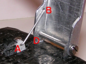
Here is a close-up picture of the implementation of the flipper linkage in R.O.N.N.Y. With the flipper at maximum height the servo arm pokes through the hole in the body. The linkage and flipper hinge can clearly be seen. The letters match the diagrams above. Point C is the servo, which is hidden inside the bodyshell.