Arduino Programming Cable
(Or, a cheap USB to UART adapter)
If you want to download sketches to an Arduino board, or if you want to connect any microcontroller UART to a modern PC, you will need some sort of USB adapter. Whilst you can buy (doubtless very good) FTDI adapters from Sparkfun and others, here's how to make your own - probably for much less money.
There are many, many “USB to RS-232” converters available cheaply on Ebay. As always, prices vary and you have to watch the shipping charges, but they are often available from reputable UK-based suppliers for less than £2 including shipping.
As USB to RS-232 converters they are sadly lacking, since the “RS-232” signals are actually just 5V CMOS, not the proper full-range RS-232 levels (+/-3V to +/-15V). This is to our advantage though, as it makes it much easier to interface these devices to 5V microcontoller UARTs. There is one complication, and that is that the RS-232 standard defines a logic '1' as a negative voltage and logic '0' as a positive voltage. Microcontroller UARTs on the other hand use conventional logic levels, '0' = 0V, '1' = +5V. A 74HC04 hex inverter IC can be used to invert all the logic signals and can be powered from the USB +5V supply.
The schematic shows the standard Arduino connector pinout and connects the USB +5V to the target board. Whilst this is handy for powering the board whilst programming, you do need to be careful that a fault on your baord doesn't short the 5V supply - potentially damaging your PC. Best to use a cheap powered USB hub to protect your PC or don't connect the +5V through to your board and power it separately.
The USB to RS-232 converters usually come built into a DB9 plug with a short cable to a USB-A plug. You could make a small board with the 74HC04 and a DB9 socket to plug into the converter, but the sockets are quite expensive to buy. I decided to strip the converter down and see how I could integrate the inverter IC.
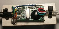
Many of the converters come in a translucent blue case which is actually a soft plastic moulded around the circuit board and connector. It is easy to remove with a craft knife, taking care not to cut into the PCB! Once the casing is removed the DB9 plug can be unsoldered, taking note of which PCB pad is pin 1.
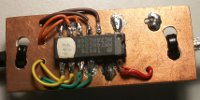
I used a scrap of copper-clad board and mounted the 74HC04 surface-mount style on one side and the USB converter on the other. Interconnecting wires go through the board and cable ties hold the USB and UART cables in place to provide strain relief. Finally the whole thing was covered with heat-shrink tubing.
A 6-way 0.1” socket connects to the Arduino pin header. Details are given in section 4.1 of the FTDI datasheet. The pinout is also shown on the schematic (above).
Many of the converters come with Windows drivers on a mini CD. Some will just be recognised by Windows and work automatically. If you have any doubts, it's best to check that the converter works before cutting it apart! The ones that I have tried have worked well with Linux (Ubuntu), appearing as ttyUSB0 with no questions asked. They have also been supplied with Windows drivers which worked as expected.