Quick & Dirty Iambic Keyer
Having received a nice shiny new Kent twin paddle morse key for Christmas, I was faced with finding a way to learn to drive the thing before going on air! Although my radio has a built-in keyer, it only operates on transmit so I would have to run the radio into a dummy load and would be confined to the (freezing cold) attic for my practice sessions. What I needed was a small, portable keyer plus practice oscillator that would drive a pair of headphones and allow me to practice in comfort without disturbing the rest of the family.
Rummaging around in my “junk box”, I found an Atmel ATTiny45 8-pin microcontroller which has just enough I/O pins to do the job. I decided that the circuit needed to be battery powered for portability and I happened to have a battery holder for two AA cells, so that defined the supply voltage. The ATTiny45 will work happily down to at least 2.7V (1.8V for the ATTiny45V).
I wanted to be able to easily adjust the keyer speed as my sending (hopefully) improved. The ATTiny45 incorporates a 10-bit ADC so I decided to add an analogue speed control via a potentiometer, with suitable minimum and maximim speeds.
I needed to use one of the ATTiny45's timers to time the “dit”s and “dah”s, and fortunately it has a second timer with PWM output which made generating a sidetone very simple. A straight keyed output is used to drive an LED, although it could equally well be used to key a transmitter.
Two inputs are needed to handle the “dot” and “dash” paddles, making a total of five I/O pins with the speed control input, sidetone and keyer outputs. The ATTiny45's reset pin may be used as an I/O pin, but this prevents the device from being re-programmed in circuit which was essential for software development. So all the available I/O pins are used, and with just six external components it is possible to construct a fairly compact keyer and practice oscillator.
Resistor R1 sets the sidetone volume. 10k worked well with the Walkman-style earphones I had to hand. Although the sidetone is a square wave it sounds surprisingly OK. A small capacitor across the headphone terminals could be added to roll off the high frequency harmonics if you prefer a more mellow sound.
The potential divider formed by R2, RV1 and R3 set the keyer speed. R3 also ensures that the programmer's clock signal is not shorted to 0V when the speed is set to minimum. The minimum voltage is 320mV, corresponding to a speed of about 12wpm. The maximum voltage is 1.4V, corresponding to about 40wpm - far faster than I am ever likely to need!
R4 limits the current through LED DS1 to 2-3mA. A low-current (or high brightness) LED may be required if you need to be able to see the LED at a distance or in bright conditions. The 5mm green LED I had to hand is perfectly visible in normal indoor conditions.
The programming connector is a 6-pin header following the standard Atmel ISP pinout. The headphone socket is a 3.5mm stereo jack socket wired with the left and right channels in parallel. The key socket is a 1/4” jack socket wired the same as my radio. The battery connector is a PP3 battery snap that mates with the 2xAA cell battery holder.
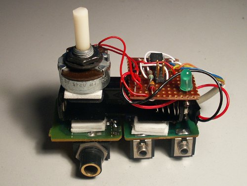
As I wanted to build the keyer quickly over the Christmas holidays, all the parts had to come from my “junk box” so the circuit is built on a small scrap of Veroboard. The jack sockets were recycled from old audio equipment, hence the PCBs and the fact that there are two headphone sockets.
The battery holder provided a convenient base to mount everything on, using double-sided sticky pads. A really “ugly” construction method!
I found that the keyer worked very well, and within a few days I was confident enough to take to the air, albeit with some rather wobbly sending at times.
The software for the keyer project is available here.